Version 2 (Final Prototype)
The focus for this page will be new concept path that I am going down. As a reminder, below is the concept image I had drafted when decided to go down this path of development (Note that this is the same one that appears on the Prototype Development Main Page):
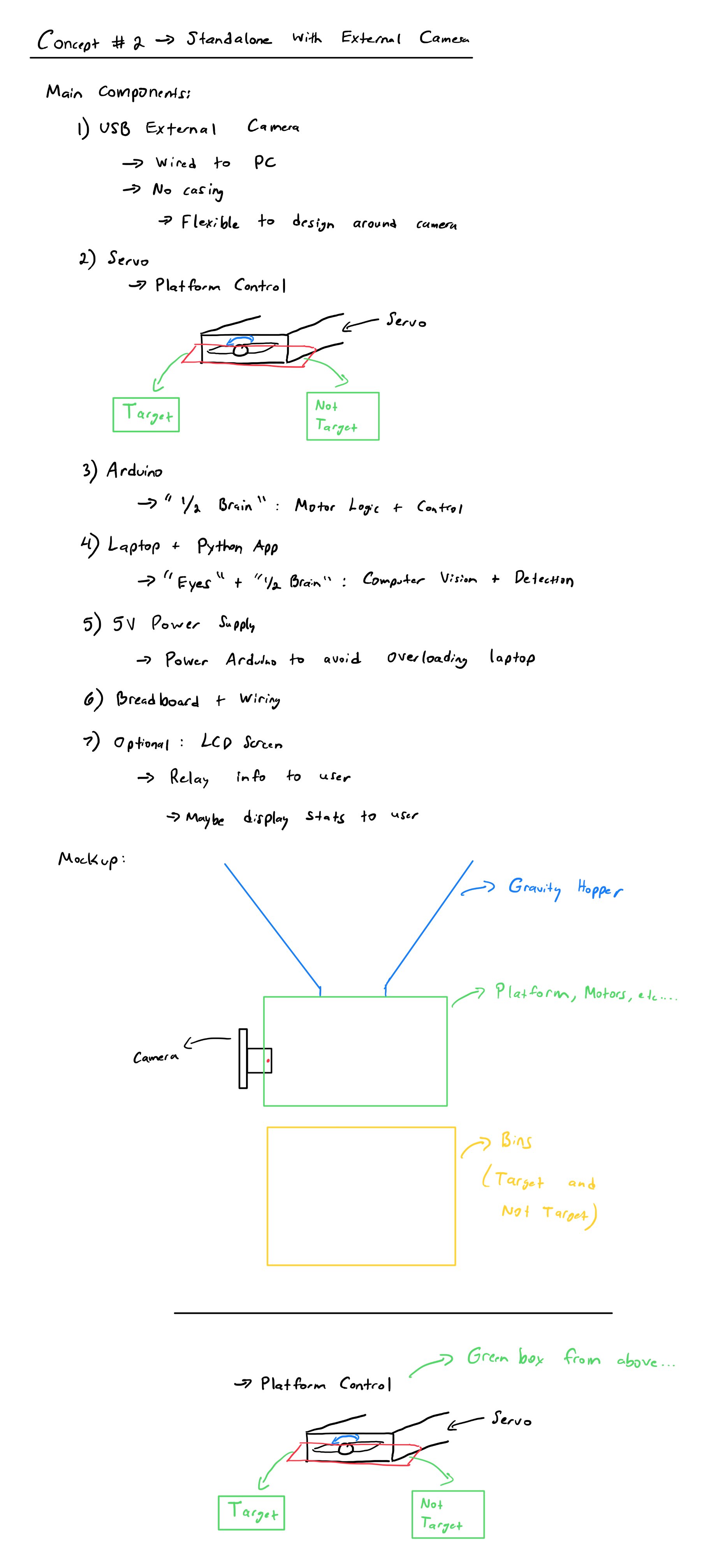
Note that there are a few changes from the concept image to the prototype:
-
No inclusion of a gravity hopper: As mentioned a few times across the documentation, object feeding can be considered more of a feature that is nice to have, rather than a requirement for the prototype. In addition, developing a system to feed any kind of objects that have the same relative volume is something more challenging than initially expected. Thus, it makes the most sense to focus on the object detection and sorting more than the feeding into the system, as objects can be manually fed.
-
LCD Screen is included: Above, an LCD screen was listed as an optional feature, however, I have decided to include it on the design. One thing to note is that the LCD working is considered lower priority as it is not important to have that working for the prototype to work.
-
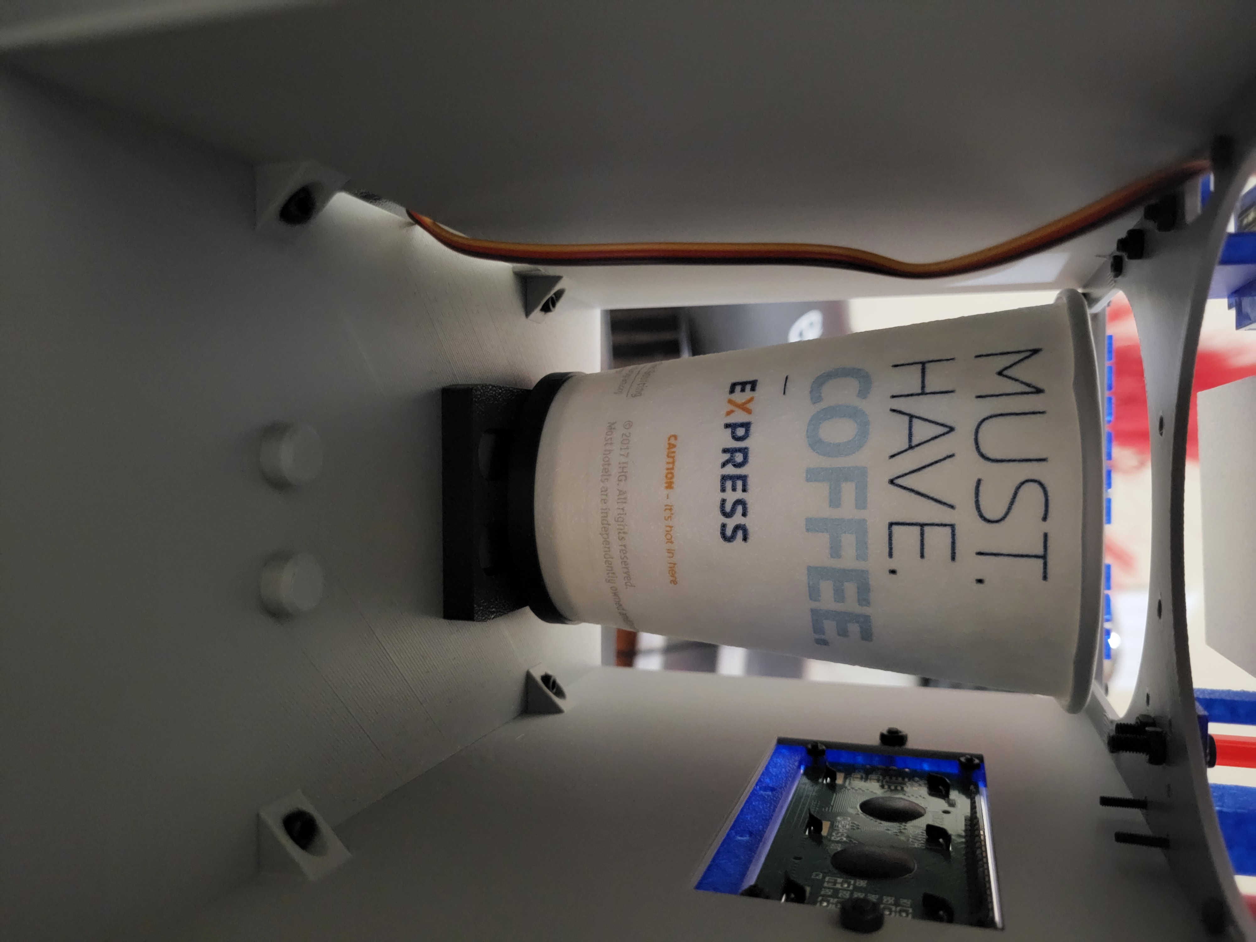
Camera Orientation: On the concept image, the camera orientation is mounted such that objects would fall into view from up to down and along gravity and the camera would be mounted somewhere on the side to be able to see the object. Upon further reflection, it makes more sense to have the camera be top mounted. This is down to the fact that flat objects such as coins can be made more visible from above, and it won't impact the camera's ability to view other classes of objects. In hindsight, this orientation change helped, as the camera sourced for this project is very zoomed in and has a narrow FOV, which meant I had to mount the camera about 7 inches from the viewing platform. This would not have been possible if I had mounted the camera to face sideways instead of looking down at the objects.
Version 2.1
Below is a table of components (not including those in CAD) that need to be integrated. Note that prices are listed in USD and are reflective of those found in early October 2025.
| Component | Picture | Estimated Unit Cost (on Amazon) |
|---|---|---|
| Walfront USB Camera Module, HBV-W202012HD | 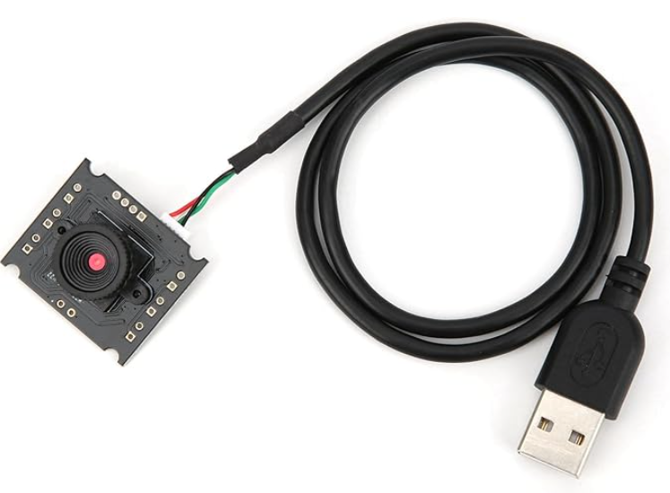 |
~$11-12 |
| MicroServo 9G (SG90) | 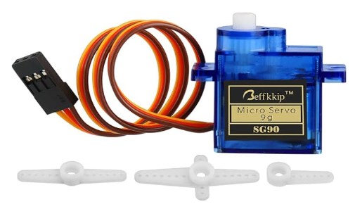 |
~$2 (comes in a 4 pack for ~$8) |
| Arduino Leonardo (NOTE: Any microcontroller can be used as long as it meets your requirements) |
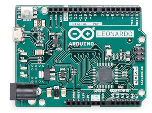 |
~$25 |
| Laptop (NOTE: Laptop must be able to run Python and YOLO, which requires either a decently strong CPU and/or a dedicated GPU. I have the HP ENVY x360 2-in-1 Laptop 15-ew1xxx.) See Geekbench here for detailed info about my laptop's specs. |
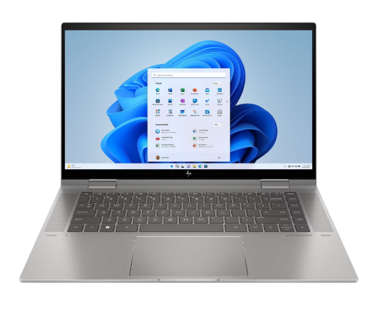 |
~$800 |
| 3.3V/5V Breadboard Power Supply Module | 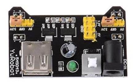 |
~$1.80 (comes in a 5 pack for ~9) |
| Breadboard and Jumper Cables (and LEDs if desired) | 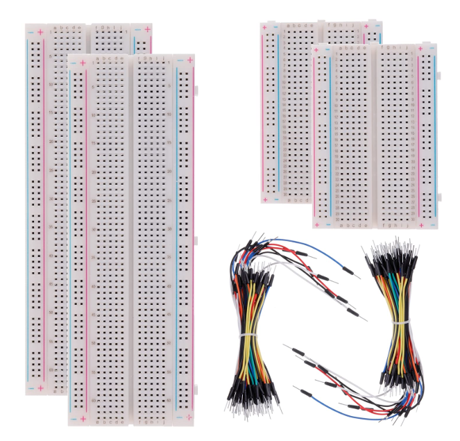 |
~$10 (for full pack as pictured) |
| 1602 LCD Screen | 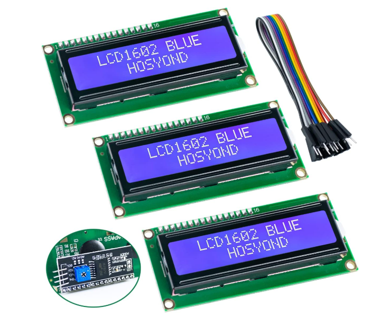 |
~$4.33 (comes in a 3 pack for ~$13) |
| AC Adapter (9V, 1A Output) |  |
~$8 |
Arduino/Microcontroller Pin Usage
An Arduino Leonardo has a total of 12 Digital Pins (7 of which are PWM) and 6 Analog Pins. Before thinking about the CAD, it is important to see how many pins are used for what is listed above. This provides a good baseline and is able to inform future improvements.
Click to view a great article that details information about the Arduino Leonardo and its pins.
| Electrical Component | Description | Pins required on Arduino |
|---|---|---|
| Green LED | Lets user know that an object can be fed into the system for sorting | 1 Digital PWM Pin |
| Red LED | Lets user know that an object can NOT be fed into the system for sorting | 1 Digital PWM Pin |
| Servo | Rotates platform to send object to target or not target bin | 1 Digital PWM Pin |
| LCD Screen | Lets user know status of system without having to look at Python interface; Displays stats to user at the end of sorting session | 6 Digital Pins |
One of the things I was initially considering was including a gate to physically stop objects from being fed, however that is not necessary on the prototype. Ultimately, I picked including a screen over a gate, due to constraints on pins. This can be considered another improvement that would be nice to have.
Since most of the pins left are analog pins, this leaves room to include any sensors that may be needed should the information from the camera not be enough for the system to work properly.
CAD
I used Onshape to create the CAD for this prototype, and you can view the CAD by clicking here.
Picture Galleries of CAD:
Various galleries are below to show more details about the components and subassemblies of the CAD. Click thumbnail to enlarge the images.
Camera Mounting Subassembly:
Sorting System Subassembly:
Body Subassembly:
Full Assembly:
Prototype Production
A total of 5 colors were used throughout the printing process. I am listing the color as well as the brand and type of filament.
- White (Bambu Lab PLA Basic)
- Black (Bambu Lab PLA Basic)
- Light Grey (Bambu Lab PLA Basic)
- Transparent Red (SUNLU Transparent PLA)
- Transparent Blue (SUNLU Transparent PLA)
Most of the slicing settings are pretty much left untouched, however, there are some notable settings that I used:
- Infill Pattern: Gyroid
- Infill Density: 15% (can probably go as low as 7-10%)
- Wall Loops: 2
- Supports: Normal supports with default settings (not tree supports)
Everything else was left as the default settings found in Bambu Studio.
Below are some details that summarizes all relevant details after slicing in Bambu Studio:
Total Filament Usage (Including Supports):
| Color | Filament Used |
|---|---|
| White | 18.76 g |
| Black | 35.00 g |
| Light Grey | 288.22 g |
| Transparent Red | 91.41 g |
| Transparent Blue | 31.82 g |
| Total | 465.20 g |
Costs:
Regardless of actual filament, assume that all filament is acquired at the rate of $23/kg, which is similar to how much Bambu Lab PLA Basic filament costs.
Total Cost = $0.023/g * 465.20 g = $10.70
Time:
Total time spent printing is calculated at 13 hours 56 minutes (across 7 plates) according to Bambu Studio using default settings for speed.
Assembly
Below are a few tables that show a list of components and hardware required:
| 3D Printed Part | Subsystem | Quantity |
|---|---|---|
| Camera Frame Corner Sleeve | Camera Mounting | 4 |
| Camera Frame | Camera Mounting | 1 |
| Top Plate | Camera Mounting | 1 |
| 12-14oz Coffee Cup | Sorting | 2 |
| Cup Base | Sorting | 2 |
| Cup 'Washer' | Sorting | 2 |
| Cup 'Drawer' | Sorting | 2 |
| Platform | Sorting | 1 |
| Ramp | Sorting | 1 |
| Servo Mount | Sorting | 1 |
| Platform | Sorting | 1 |
| Base | Body | 1 |
| Bottom | Body | 1 |
| Bin Label Plates | Body | 2 |
| LCD Screen Frame | Body | 1 |
| Shell | Body | 1 |
| Electrical Component | Quantity | Purpose |
|---|---|---|
| 1602 LCD Scren | 1 | Display key information and statistics to user |
| Green LED | 1 | Tells user object can be fed |
| Red LED | 1 | Tells user objects can NOT be fed |
| 10kΩ Potentiometer | 1 | Controls screen brightness |
| MicroServo 9G (SG90) | 1 | Rotate platform to move object for sorting into 'Target' or 'Not Target' bin |
| Walfront Camera Module | 1 | External USB Camera to provide view of object for YOLO to process |
| Arduino Leonardo | 1 | Communicates back and forth with Python app to perform key functions |
| Breadboard | 1 | Connects Arduino to External Power Source |
| Breadboard Power Supply Module + AC Adapter | 1 | Powers Servo, LCD Screen, and Arduino to take load off of Arduino and Laptop |
| M-M Breadboard Jumper Cables | Many | Creates electrical connection between components, power source, and Arduino pins without soldering |
| F-M Breadboard Jumper Cables | Many | Creates electrical connection between components, power source, and Arduino pins without soldering |
| Quantity x Screw Size | Purpose |
|---|---|
| 4 x M3 | Mounts Shell to Bottom; Threads + Nut Sticking out sits flush with base |
| 2 x M3 | Mounts LCD Screen Frame to Shell |
| 4 x M2 | Mounts 1602 LCD Screen to LCD Screen Frame |
| 2 x M3 | Mount Cup Washer + Cup Base + Cup 'Drawer' |
| 4 x M2 | Mount Bin Labels to Top of Shell |
| 6 x M2 2 x M3 |
Mount Ramp to Top of Shell (not all M2 screws needed; I used 2 x M3 and 2 x M2) |
| 2 x M3 | Mount Servo Mount to Top of Shell |
| 2 x M2 | Mount Servo to Servo Mount |
| 4 x M2 | Mount Camera Frame Corner Sleeve to Top of Shell |
| 4 x M2 | Mount Top Plate to Camera Frame |
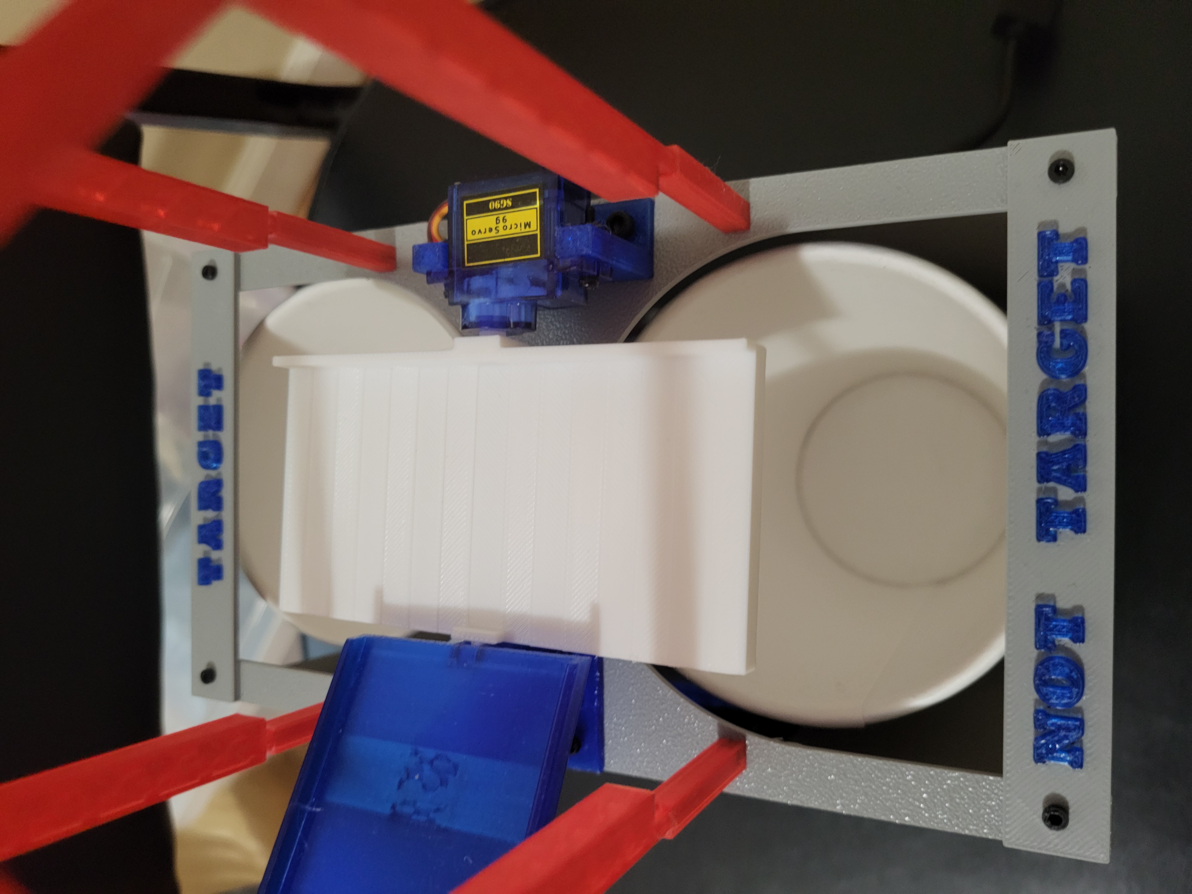
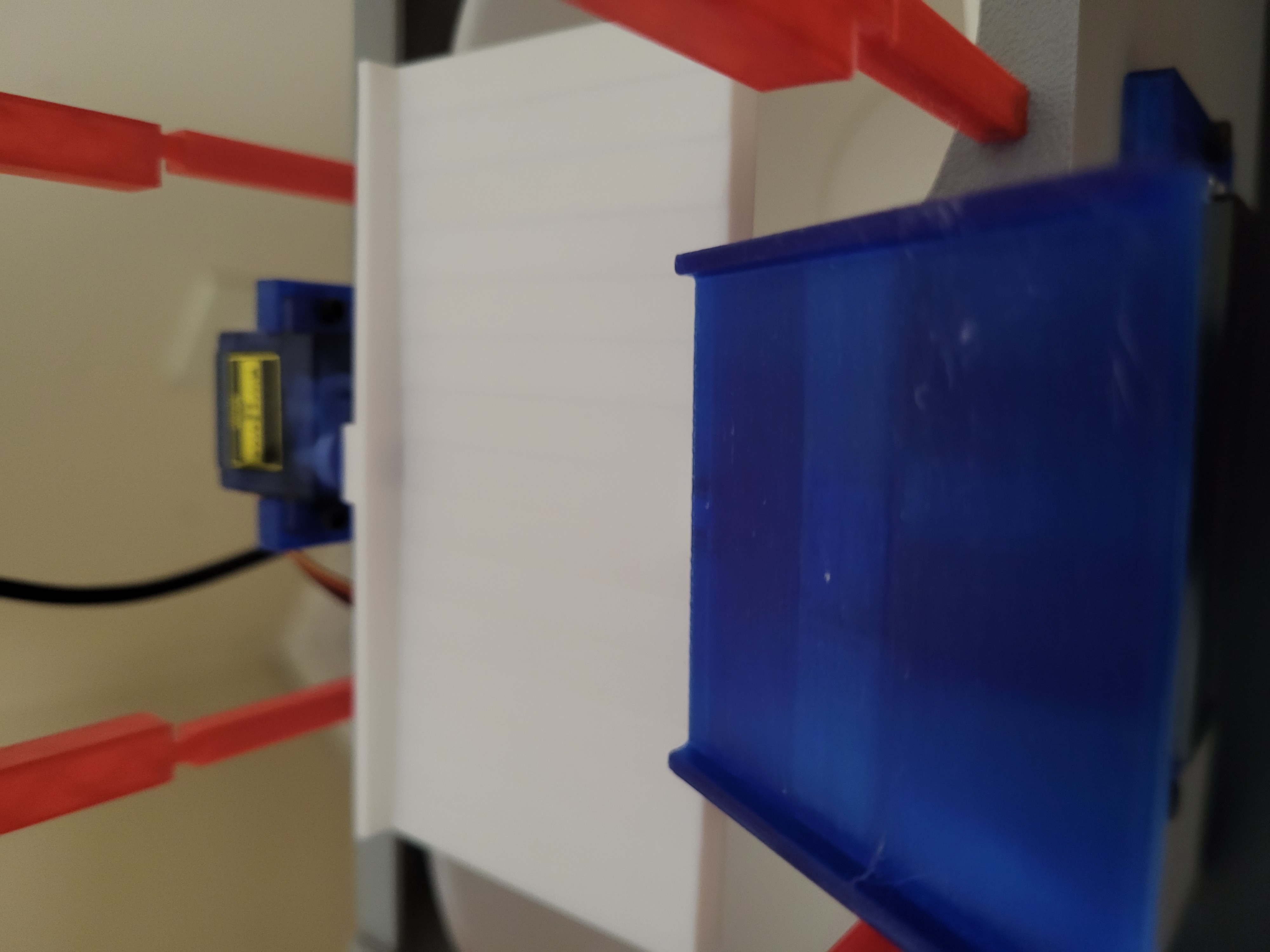
Quick Assembly Notes:
1) How to assemble platform to servo: You will notice that the platform presses directly onto the splined shaft of the servo. The way I was able to achieve this was by using some accessories you get with servo motors. First, take any arm of the servo you were given (I elected to use the single arm piece given) and cut around the center female splined portion. After that, use some super glue and glue that small part into the side of the platform that has an opening for it (should fit snug). Wait for the glue to dry before assembly. To make a stronger bond, I would suggest using something like PLA Bond to increase the strength of the bond but that is not super necessary. I used the following video for inspiration, and you can use as a refernce should you want to recreate the assembly instructions: Video.
2) The end of the Platform that has the shaft sticking out had to be sanded/filed down slightly in my case.
3) The holes on the LCD Screen Frame were originally intended to accomodate four M3 screws to hold the screen, but actually work better using four M2 screws.
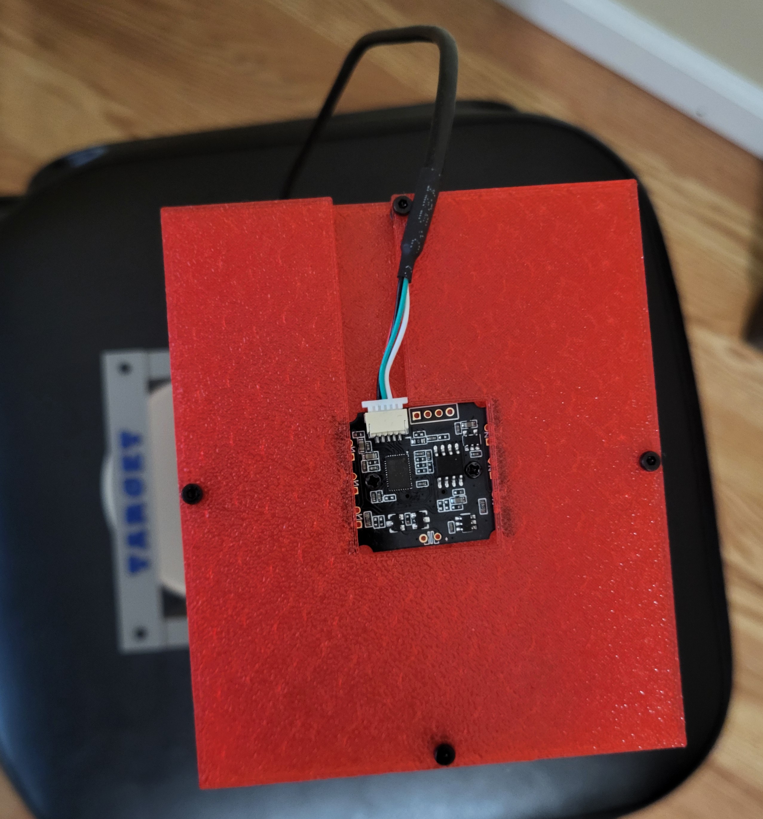
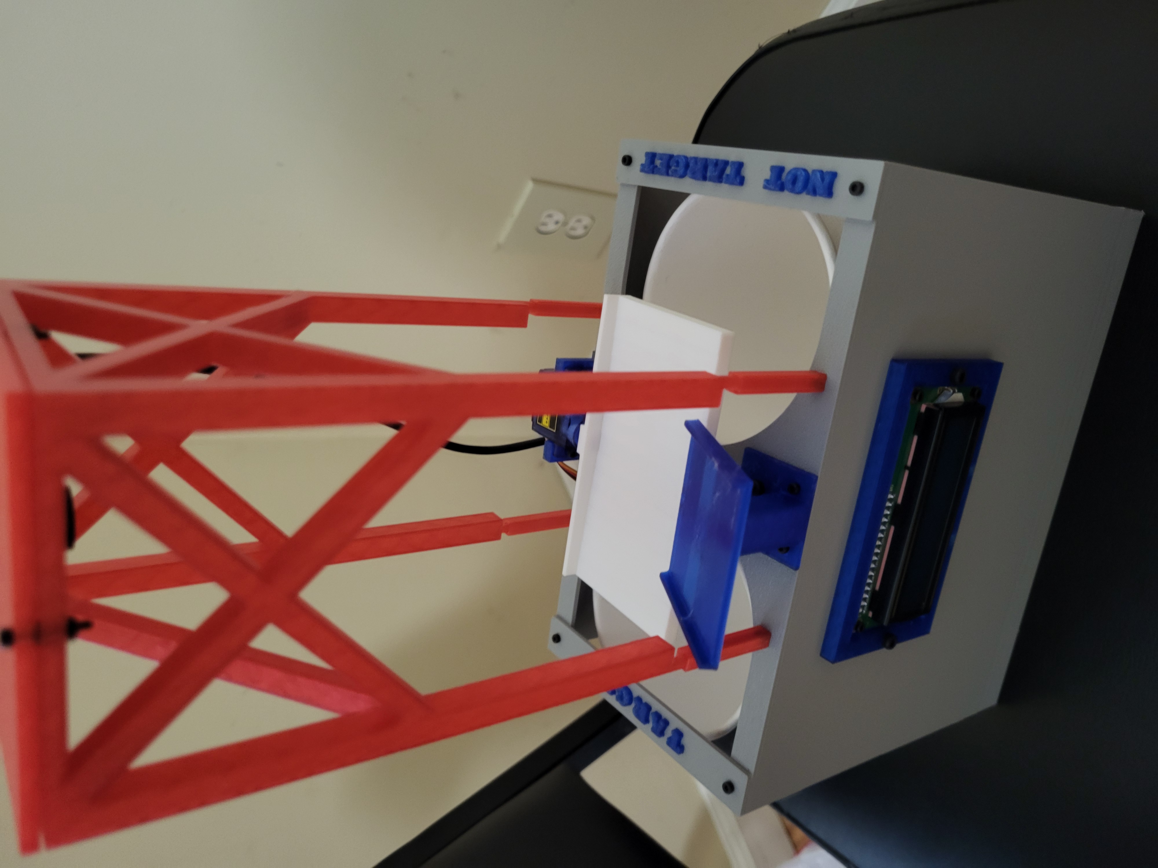
4) The Camera does not slot in anywhere, but it is instead sandwiched between the Camera Frame and Top Plate to keep it held in place.
Pictures (electronics not wired and LEDs not installed):
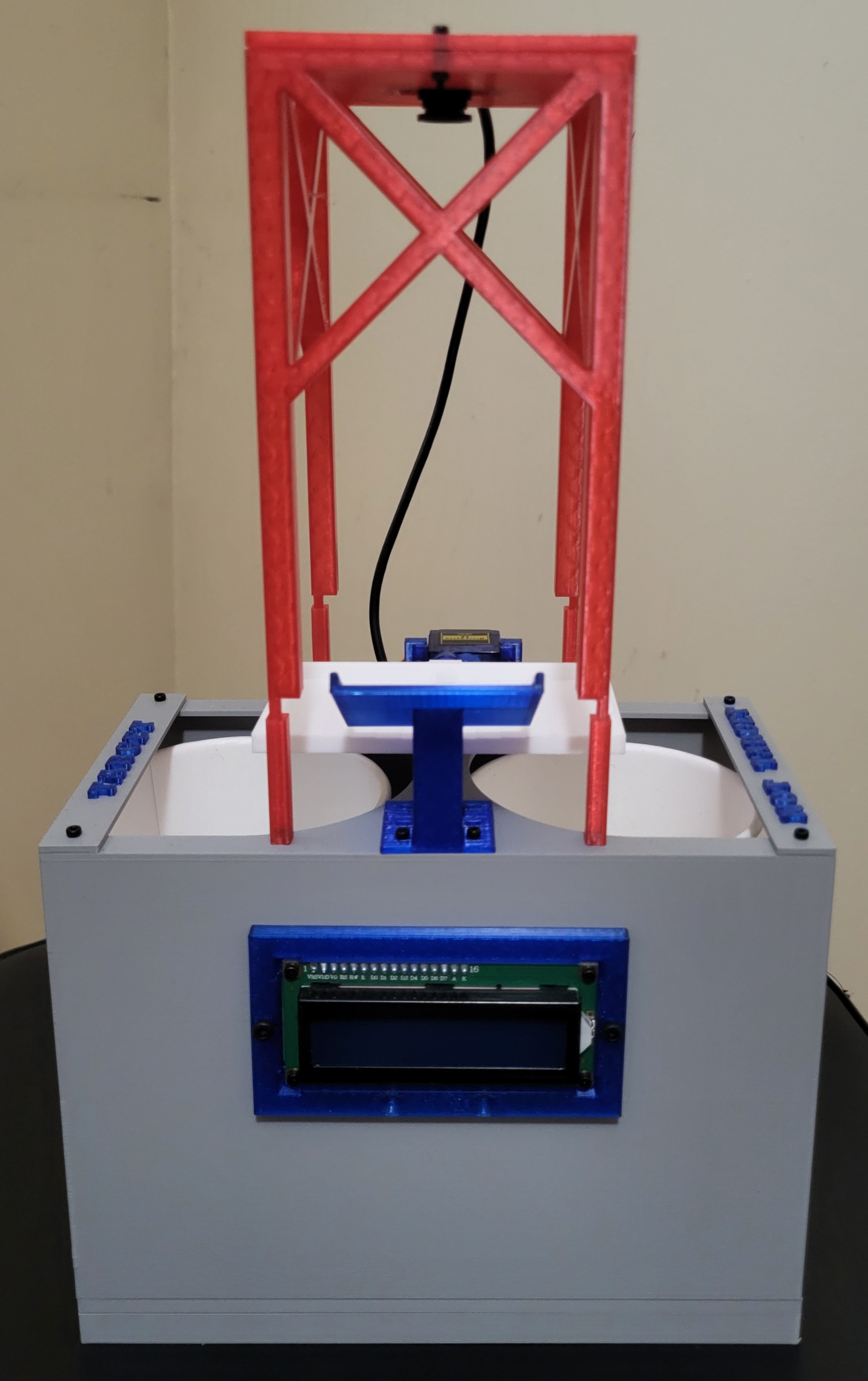
Feel free to print this out yourself! Use the .3mf if you have a slicing software that can run it, otherwise I have included the stl/step files needed. Note that the zip files will require you to manually add the names of the bins to the bin labels.
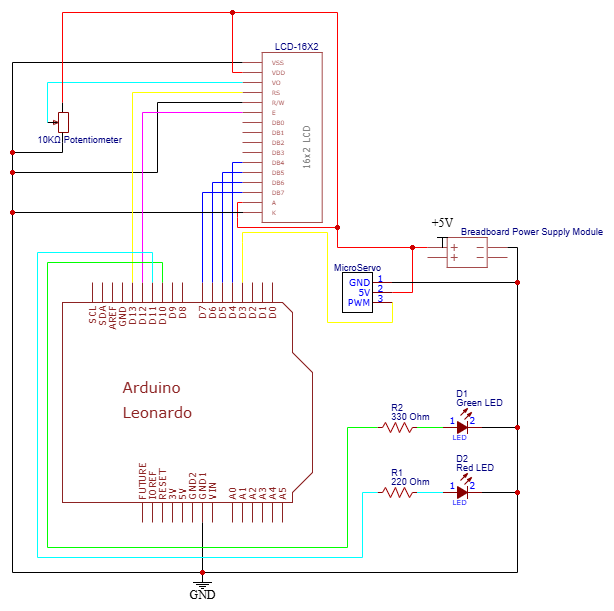
Wiring
Below is a wiring diagram:
Testing
Note that this section refers to testing beyond any fit checks and clearances between any hardware, holes, etc present while assembling the prototype. In other words, the prototype is FULLY assembled by this point and theoretically, if the Arduino code was inputted for the final product, then the system would run (i.e. no wiring changes, etc).
Before moving on to final integration, the prototype must be tested for a few things to see how it works. This is to ensure that a proof of concept for a strong path forward before working on a more advanced version of the software and integration.
Here is a list of components and/or systems that MUST function properly to ensure that the full prototype works properly:
- Green LED
- Red LED
- 1602 LCD Screen
- Servo + Platform
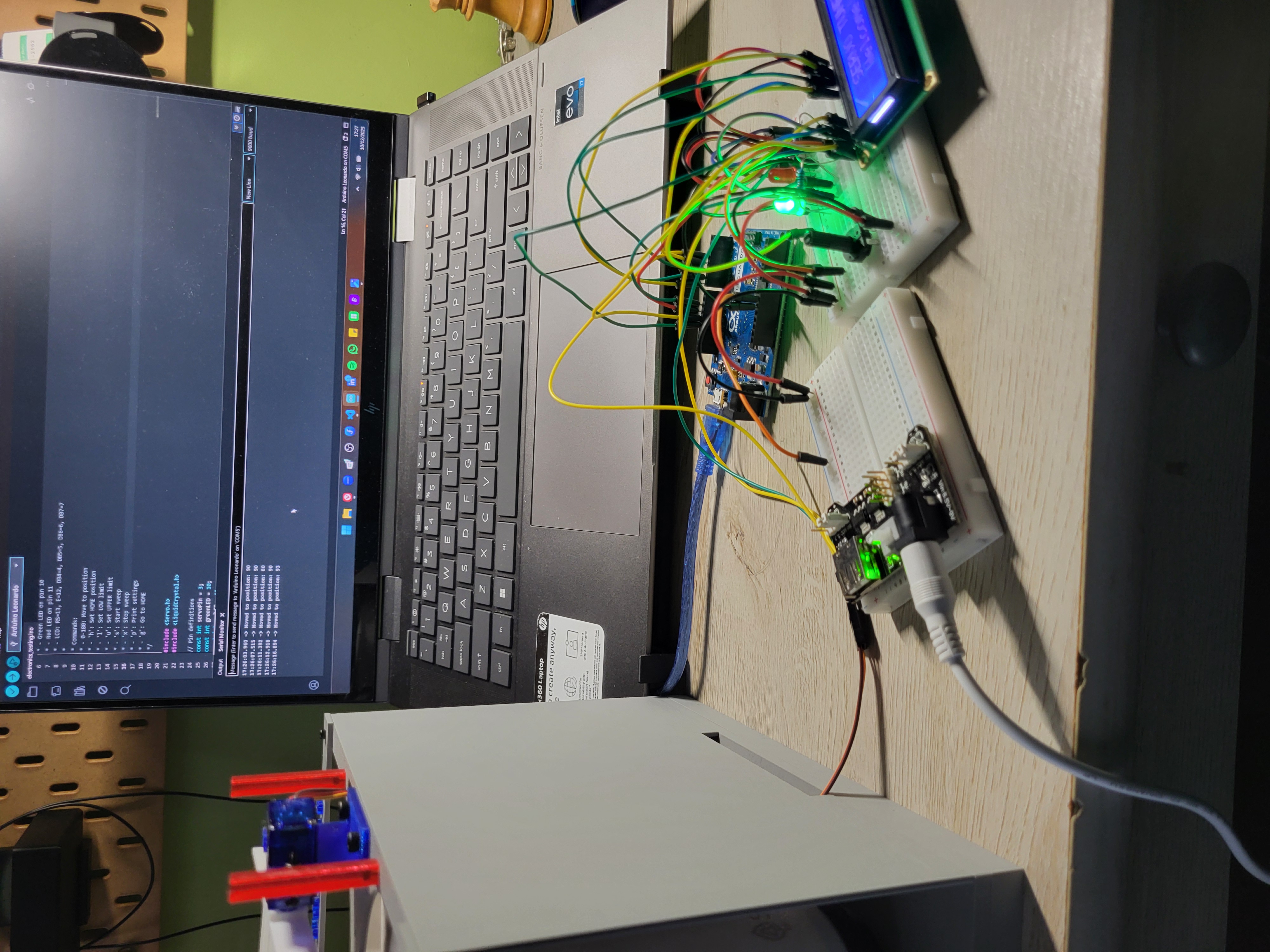
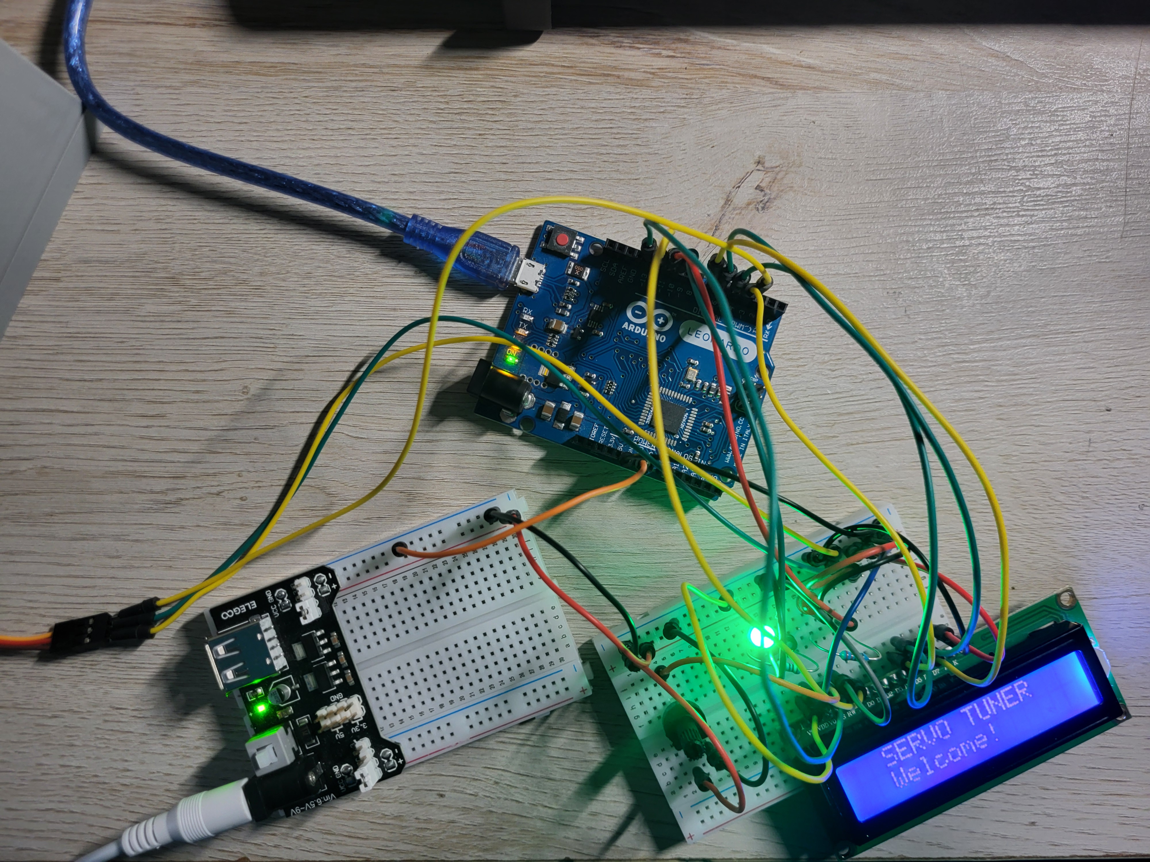
The most effective way to test everything at once is to write some code that covers across all components. The code is included below, but first, here are some of the features of the code:
- Green and Red LEDs are constantly blinking every couple seconds to ensure those are working properly.
- LCD Screen displays a welcome message and displays the angle that the servo motor is at.
- Servo and Platform rotation is tracked and can be calibrated so the correct servo angles can be inputted into the final code. Also, platform must be tested to ensure objects can actually fall into both cups for sorting, which is done manually now since the camera is not connected to YOLO.
Code below:
| electronics_testing.ino | |
|---|---|
1 2 3 4 5 6 7 8 9 10 11 12 13 14 15 16 17 18 19 20 21 22 23 24 25 26 27 28 29 30 31 32 33 34 35 36 37 38 39 40 41 42 43 44 45 46 47 48 49 50 51 52 53 54 55 56 57 58 59 60 61 62 63 64 65 66 67 68 69 70 71 72 73 74 75 76 77 78 79 80 81 82 83 84 85 86 87 88 89 90 91 92 93 94 95 96 97 98 99 100 101 102 103 104 105 106 107 108 109 110 111 112 113 114 115 116 117 118 119 120 121 122 123 124 125 126 127 128 129 130 131 132 133 134 135 136 137 138 139 140 141 142 143 144 145 146 147 148 149 150 151 152 153 154 155 156 157 158 159 160 161 162 163 164 165 166 167 168 169 170 171 172 173 174 175 176 177 178 179 180 181 182 183 184 185 186 187 188 189 190 191 192 193 194 195 196 197 198 199 200 201 202 203 204 205 206 207 208 209 210 211 212 213 214 215 216 217 218 219 220 221 222 223 224 225 226 227 228 229 230 231 232 233 234 235 236 237 238 239 240 241 242 243 244 245 246 247 248 249 250 251 252 253 254 255 | |
Below is some images and a video of how the electronics test was assembled. Note that it was not assembled on the actual prototype for two reasons:
1) To make sure the concept actually works before fully assembling it and wiring it together.
2) At the time of testing, I didn't have the necessary jumper cables to do a proof of concept test on the actual prototype. This meant that I couldn't assemble it on the actual product just yet, but I was able to test all electronics to see if it was working.
It is also important to note that some may experience difficulties with assembly and/or testing. There are generally two types of issues, one of which is software issues, and the other of which is hardware issues. Common software issues usually fall under either a code that has bugs or code that has faulty logic, both of which can still occur despite using AI tools for coding. Common hardware issues include the following: damaged Arduino pins, faulty chip on the Arduino, loose connections, faulty wires, faulty wiring, faulty breadboard, etc. The only major problem I had with the wiring was actually a faulty breadboard, which meant I had to rewire the entire circuit on a different breadboard.
The way I approached testing was to show a proof of concept for all working systems, including mechanical and electrical. The code above was able to get the electronics working, which entailed getting the platform rotated. However, the prototype will only have a good proof of concept if it can theoretically send objects to any bin while also relaying information on the screen. Something important to note is that I am manually telling the servo to move to a certain angle, whereas in the final testing, it will be automated based on the objects fed, the user demands, and of course, the pytorch model loaded.
Therefore, I decided to put it to the test by sending a small sample set of objects. Below are the exact objects I used while testing, and a ruler to give an idea of the general size of these objects:
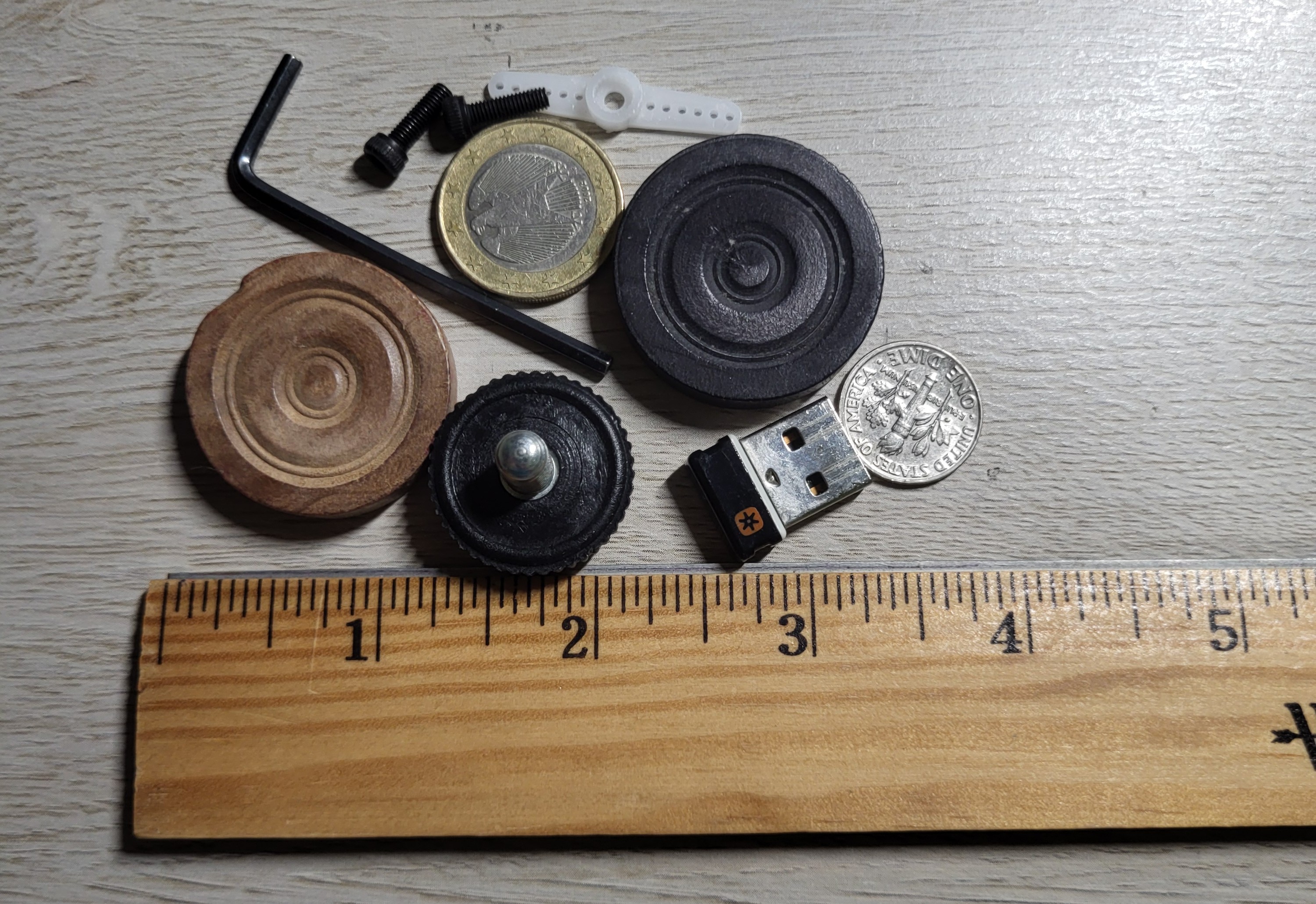
And now, the test video below:
Testing Observations:
- Using the code above, I figured out that the upper limit was 135 degrees and the lower limit was 55 degrees, which gives a sweeping motion of 80 degrees, or about 40 degrees on each side. This was more than I had expected from when I was modelling the prototype in CAD. The final tuning will be done before final testing if needed.
- All the electronics work as expected. The screen turns on, gives a welcome message, and relays the servo angles at all times when there is a change. The LCD also works as expected, and the potentiometer does, in fact, adjust the brightness as required. The LEDs alternate turning on and off while power is being given. The servo also turns as expected, which a relatively quick response time to any inputs.
Conclusion
With all the success of the assembly and testing, I think this is a solid prototype to move forward with the project.
Any changes that have to be made to the prototype are all considered minor, and will be documented and finalized in the integration stage.